Polished steel lint roller
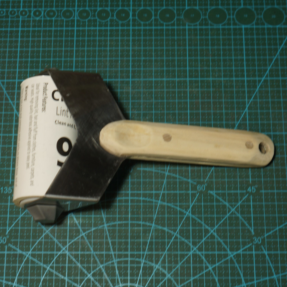
This handmade lint roller came about after experiencing several bad plastic lint rollers where the paper roll comes off, gets jammed or even pinches a finger. It looks to create an aesthetic and robust tool that rolls smoothy and is comfortable to hold. It is made of 2mm sheet steel with a pine handle and sealed ball bearings.
Initial design involved several sketches and cardboard modeling. Key limitations came from the requirement to use metal for the main frame. Initial concepts considered a 3D printed frame but after considering the forces and dynamics on the system it was determined that the layer system of 3D printing would not be sufficient. Other key limitations were to utilize off the shelf components were possible, be easy to assemble/disassemble without tools, and have good ergonomics.
This design utilizes 3D printed PLA end caps with press fit 608 ball bearings for the paper roll drum. 3D printed PLA was chosen for its low cost and ability to be quickly prototyped as well as a means to ensure that both end caps were concentric. The 608 ball bearings are of the same type as used in roller skate wheels and ensure that the axel does not wear down the soft PLA end caps. The end caps have a small taper to them to adapt to variations in paper roll size. There is also a taper on the inside side of the end caps to help guide the axel through to ease the process of changing out a paper roll.
For the axel, a 5/16 threaded rod was selected as the closest fitting off the shelf component that would fit the ball bearing center bore. A threaded rod instead of a bolt was selected due to the length of the paper roll and not finding bolts of a sufficient length. To retain the axel position, two lock nuts were chosen to serve as retaining nuts. A standard nut was also considered but there was a concern that it could come loose during use if they were not sufficiently preloaded. To assist with tightening and removing the retaining nuts, 3d printed end caps were designed. These end caps are press fit over the lock nuts and give it a larger diameter to hold on. They also have a spiralized fluted design to improve grip. The spiral direction is such that it assists with removing and limits the amount of force that can be applied when tightening. This was done to ensure that the user could not accidentally over tighten the retaining nuts and not be able to remove them. The end cap was printed using a high resolution resin printer for it's better surface quality compared to FDM printing.
The hardest and most time intensive part was the frame construction. As stated earlier, the initial prototyping was done in cardboard. Cardboard was chosen for it's thickness. When bending metal some additional length must be added to account for the amount of metal in the bending radius and cardboard does a good job of simulating this compared to card stock or something thinner. To ensure that the design was symmetric, the pattern was traced to a piece of paper, then folded in half and cut along the one of the outlines. This pattern was then traced to a piece of sheet metal. Most of the difficulty in the project came from the cutting, filing and polishing of this metal. Holes were then drilled for the axle and the bends were added using a brake press. The location of the bends was intentionally placed slightly wider than the paper roll drum. Getting the bend location perfect was unlikely and that extra width could be reduced a little by adding a slight arch to the frame for fine tuning.
The final step was handle construction. For this, some scrap pine from a broken shelf bracket was used along with some quarter inch hard wood dowel from a previous project. The pine was cut to sized and chamfered to a comfortable fit in the hand. On the top scale, a thumb divot was added and on the bottom a small horizontal groove was added for index finger placement. These ergonomic considerations were not strictly necessary but add a nice touch. Afterwards, the scales and frame were clamped together and drilled in one process to ensure alignment. To attach the scales to the handle an adhesive was used and the hard wood dowel was pressed through the holes in the handle. Final processing involved shaving down the dowels and sanding the edges if the handle.
A small electric motor for a bicycle
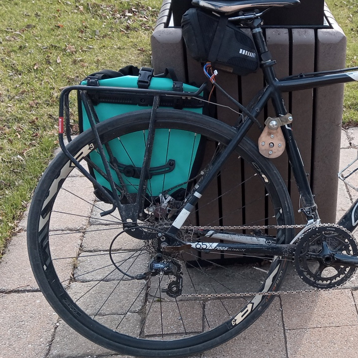
A typical commute to work and back is 40km and involves several steep inclines. This is within the range of challenging but manageable on a few days a week basis. In an effort to make this a more common occurrence, a small friction drive system was devised and implemented. This project was intended as a test to see if a small motor would would significantly improve the commuting experience. Key aspects of this system was that it must be easily removable, possible to create without metal working tools, and integrate well with the rest of the bicycle when not in use.
This system utilizes a 170KV brushless motor paired with two 3S 5.1Ah batteries in parallel and controlled with a 150A ESC. Setting the speed and activating the system is done with an ATtiny85 microprocessor which is fitted into a 3D printed bar end plug. A small push switch is integrated into the hoods of the break/shift levers of the bike. Control wiring is passed along the rear break cable and exits near the saddle. The controller and batteries are stored in the saddle bag just above the motor which is affixed to the seat tube. When the system is activated, the motor pivots on the axle and and comes into direct contact with the rear tire transferring energy to the wheels. When the system is deactivated, the force of gravity pulls the motor down and it pivots away from the tire allowing the bike to move without the additional friction of the attached motor.
The PWM controller that was developed for this project is fairly straight forward. An ATtiny85 microprocessor is configured to read a variable resistance potentiometer which is used to set the speed. This potentiometer is attached to the cap of the bar end plug. By rotating the cap, the speed of the motor can be adjusted. Another input is from the right brake/shift lever to tell the system if the motor should be turned on or off. A tact switch was selected for this function to ensure that if there was any need to quickly switch to braking that the motor would cut out as soon as the button was released.
The design for the motor mount was done in such a way that the motor could easily be removed if the bicycle needed to be locked up outside. There is a thick resin printed block that attaches to the seat tube of the bike and has a hole for the pivot axle of the motor mount. This pivot axle is a carriage bolt with a 3D printed knob attached to the head which threads into an embedded lock nut in resin block. Between the two is the plywood motor mount. By unscrewing the pivot axle, the motor can be completely removed from the bike without any tools.
Performance of the system was surprisingly good for a proof of concept and remained in use for a season. The PWM controller worked well however it would have been good to write in a momentary full speed signal when activating the system to help the motor pivot up to the wheel. There were some concerns about the rigidity of the system since fairly soft materials were used but this did not end up being an issue. The removal and reattachment of the motor also worked very well without much need to tweak the system after reattachment.
Conway's Game of Life integration
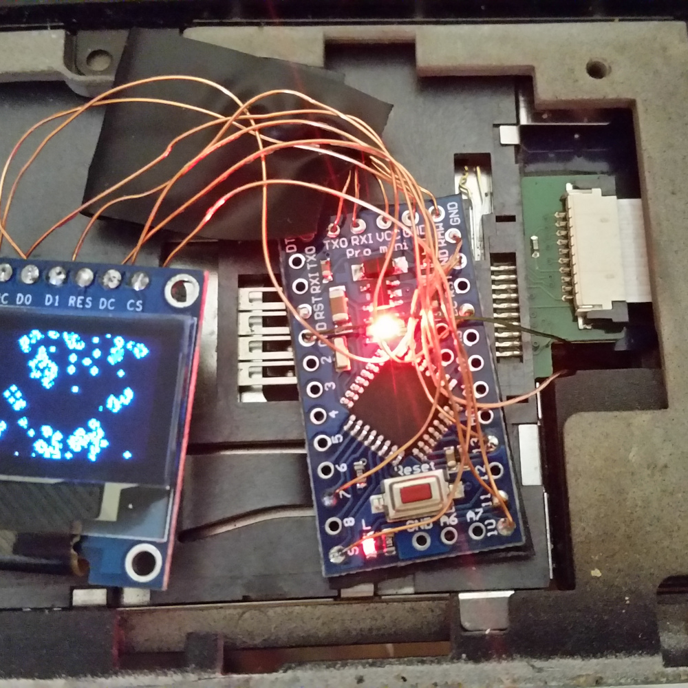
TPaulRB wrote a version of Conway's Game of Life for the Arduino and 128x64 OLED screen Link. That code was paired with an Arduino Pro Mini and embedded into a laptop palm rest as an interesting distraction when taking a break from typing. Power for this project was taken from the eSATA adapter between the HDD and the motherboard. A risky choice for sure but in the last 11 years of using that laptop, not problems ever arose with the HDD.